Home / Capabilities
Capabilities, process and testing
How an order moves from your design to a tested assembly at your door, what we test, and what ships with every lot.
Built to IPC/WHMA-A-620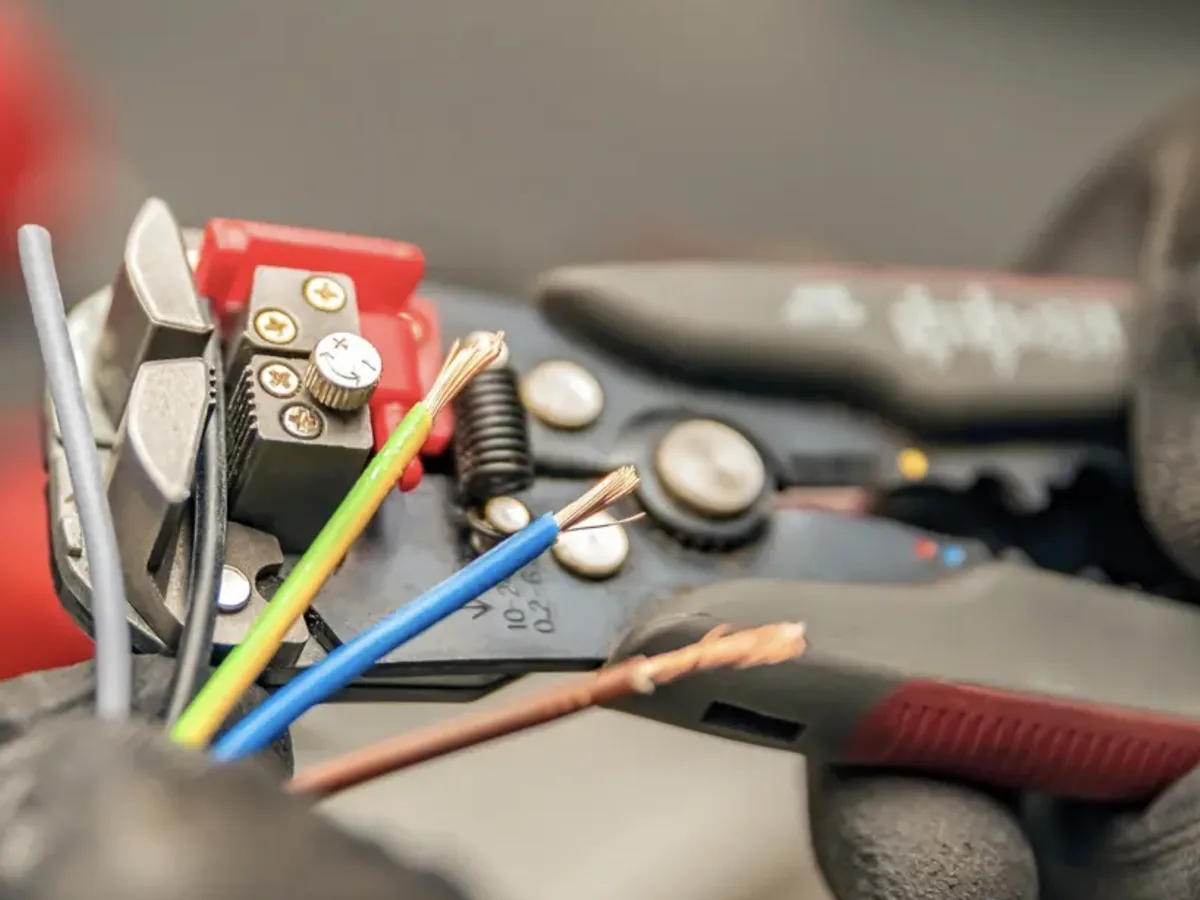
From upload to your door.
An engineer checks every pinout before we build. A swapped pin can destroy a driver board, so this step is never skipped.
Upload design
Drawing, pinout, BOM or photo.
You · minutesFiles receivedEngineering review
DFM check, price and ship date.
Same business dayQuote + draft drawingApprove drawing
You sign off the pinout and BOM.
YouApproved drawingBuild and test
IPC/WHMA-A-620 build, 100% tested.
24 hoursTest report + CoCDeliver
To your door in the Bay Area, or overnight.
48 hoursTraveler + lot codes24-hour build applies to standard builds with in-stock connectors. Larger lots are quoted with a firm date.
What we test, and how it reads in your report.
Pick a test to see what it proves and the matching line from a sample report.
Continuity, open and miswire
Every circuit lands on the right pin, with no opens, shorts or miswires.
- Method
- Each net driven from P1, sensed at P2; all nets scanned
- Requirement
- Per pin assignment · ≤ 3 Ω per circuit
- Frequency
- 100% of assemblies
| Test | Requirement | Measured | Passed | Status |
|---|---|---|---|---|
| Open, short and miswire | Per pin assignment | No opens, shorts or miswires | 10 / 10 | PASS |
Shorts and isolation
No circuit touches another anywhere in the assembly.
- Method
- Each net vs. all others tied, 100 VDC
- Requirement
- ≥ 100 MΩ
- Frequency
- 100% of assemblies
| Test | Requirement | Measured | Passed | Status |
|---|---|---|---|---|
| Shorts and isolation | ≥ 100 MΩ | > 2 GΩ | 6 / 6 | PASS |
Insulation resistance
Insulation holds at test voltage, so there's no leakage path between conductor groups.
- Method
- Group A vs. group B + shield, DC test voltage, timed dwell
- Requirement
- e.g. ≥ 10 MΩ at 300 VDC
- Frequency
- Per drawing
| Test | Requirement | Measured | Passed | Status |
|---|---|---|---|---|
| Insulation resistance | ≥ 10 MΩ | > 500 MΩ | 10 / 10 | PASS |
Dielectric withstand (hipot)
No breakdown when high voltage is applied between line conductors and ground.
- Method
- Line conductors tied to HV, ground to return, leakage measured
- Requirement
- e.g. 1.50 kV AC, 1.0 s, ≤ 5 mA
- Frequency
- Power assemblies and whips
| Test | Requirement | Measured | Passed | Status |
|---|---|---|---|---|
| AC withstand (hipot) | Total leakage ≤ 5 mA, no breakdown | 1.16–1.28 mA total | 3 / 3 | PASS |
Contact and conductor resistance
4-wire measurement of each power path, connector to connector, without lead error.
- Method
- Kelvin (4-wire) measurement per circuit
- Requirement
- e.g. ≤ 3 Ω per circuit
- Frequency
- On request
| Test | Requirement | Measured | Passed | Status |
|---|---|---|---|---|
| Contact resistance, power | ≤ 3 Ω | 0.052–0.061 Ω | 10 / 10 | PASS |
Differential impedance (TDR)
Controlled-impedance pairs hold their target along the full length.
- Method
- Time-domain reflectometry, differential, 200 ps rise
- Requirement
- e.g. 90 Ω ± 15% or 120 Ω ± 15 Ω
- Frequency
- On request
| Test | Requirement | Measured | Passed | Status |
|---|---|---|---|---|
| Differential impedance, D+/D− | 90 Ω ± 15% | 86.2–92.7 Ω | 5 / 5 sampled | PASS |
Crimp pull force
Each crimp holds above the minimum pull-out force for its wire gauge and terminal.
- Method
- Terminal held in jaw, wire pulled at constant rate to release
- Requirement
- Per gauge and terminal, e.g. ≥ 80 N for 18 AWG
- Frequency
- Per terminal lot
| Test | Requirement | Measured | Passed | Status |
|---|---|---|---|---|
| Crimp pull force, 18 AWG | ≥ 80 N (per drawing) | 109 N, 114 N | 2 / 2 | PASS |
Crimp cross-section
A sectioned crimp confirms full compaction, symmetry and no voids.
- Method
- Crimp sectioned, polished and measured under magnification
- Requirement
- Per terminal manufacturer
- Frequency
- First article, on request
Visual inspection
Crimps, solder joints, strip lengths and labels checked against IPC/WHMA-A-620.
- Method
- Stereo microscope, 10–40×, against IPC/WHMA-A-620 criteria
- Requirement
- IPC/WHMA-A-620, up to Class 3
- Frequency
- 100% of assemblies
| Test | Requirement | Measured | Passed | Status |
|---|---|---|---|---|
| Visual inspection | IPC/WHMA-A-620 Class 2 | Accept | 10 / 10 | PASS |
Flex, thermal and vibration
Cycling to your test plan with continuity monitored throughout.
- Method
- Flex, thermal-cycle or vibration per customer plan
- Requirement
- Per customer test plan
- Frequency
- On request
A formal drawing with every order.
Pin assignment, wire table, bill of materials, test spec and revision. You approve it before we build, and every rerun matches it.
Example drawing, BAH-1050 rev A: pwrCAN cable, XT30 2+2 female to female, 2,000 mm.
Shop capabilities
| Wire range | 32 AWG micro-coax to 4/0 AWG battery cable |
| Terminations | Crimp, solder, IDC, lug and ferrule |
| Protection | Heat shrink, braided and expandable sleeving, convoluted loom, tape |
| Shielding | Foil and braid termination, drain wires, 360° backshells |
| Marking | Printed heat-shrink labels, wire markers, flags, serialized tags |
| Quantities | 1 piece to production runs |
| Workmanship | IPC/WHMA-A-620, up to Class 3, the highest class |
| Materials | Authorized distributors only, RoHS and REACH documentation |
What ships with every lot
- Drawing: approved pinout, wire table and BOM.
- Test report: results for every test on your drawing.
- Certificate of conformance: signed for the lot.
- Traveler: wire and connector lot codes.
- Material declarations: RoHS and REACH on request.
Factory-terminated high-speed assemblies such as DAC, AOC and fiber are sourced from qualified manufacturers, then labeled, tested for continuity and kitted with your order.
Want a sample? We'll deliver one for free.
Tell us what you're building. We'll build a sample assembly to your spec and bring it to your door anywhere in the Bay Area, so you can check our work on your own bench.
Get my free sampleTakes 30 seconds. No account, no commitment.